|
Product Details:
|
|
| Place of Origin: | China |
|---|---|
| Brand Name: | Jekit |
| Model Number: | CP9665 |
|
Payment & Shipping Terms:
|
|
| Minimum Order Quantity: | 1set |
| Price: | factory price |
| Packaging Details: | Box Size 45*45*45cm |
| Delivery Time: | 4-7 days |
| Payment Terms: | Western Union/Paypal |
| Supply Ability: | 600 sets per Month |
|
Detail Information |
|||
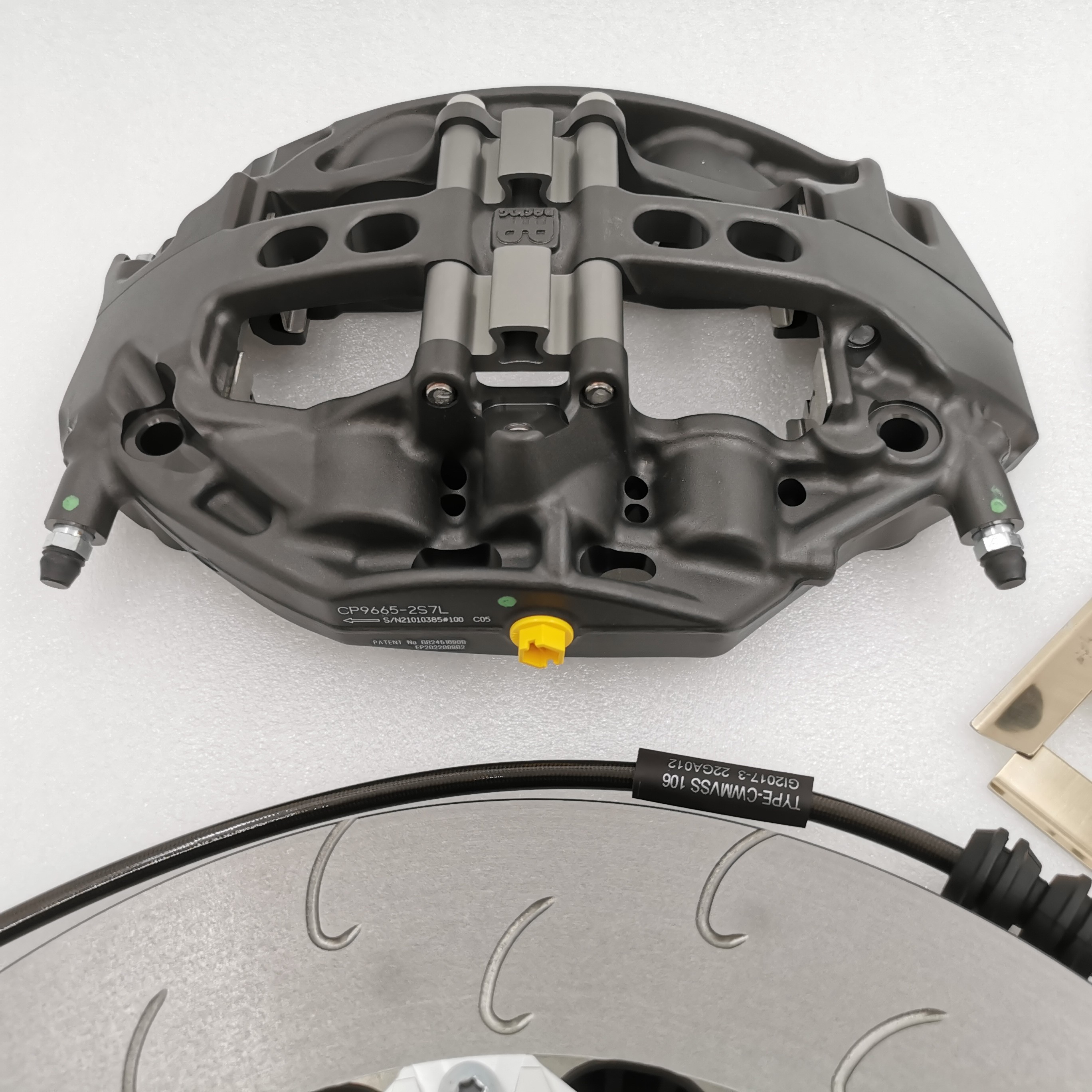
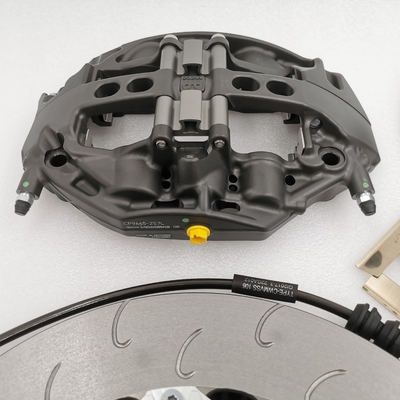
| Item Name: | 6 Pot Brake Kit | Caliper Number: | CP9665 |
|---|---|---|---|
| Brake Disc Diameter: | 390mm | Disc Thickness: | 36mm |
| Fit Wheel Rim: | Rim 20 | Disc Material: | Grey Cast Iron |
| Caliper Material: | Cast Aluminum | Caliper Color: | Grey Caliper |
| Delivery Time: | 7 Days | Bell Type: | New Sliver Bell |
| Caliper Logo: | AP Racing Logo | ||
| Highlight: | CP9665 6 Pot Brake Kit,6 Pot Brake Kit NMW F80 |
||
Product Description
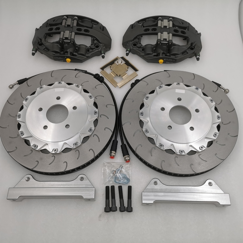
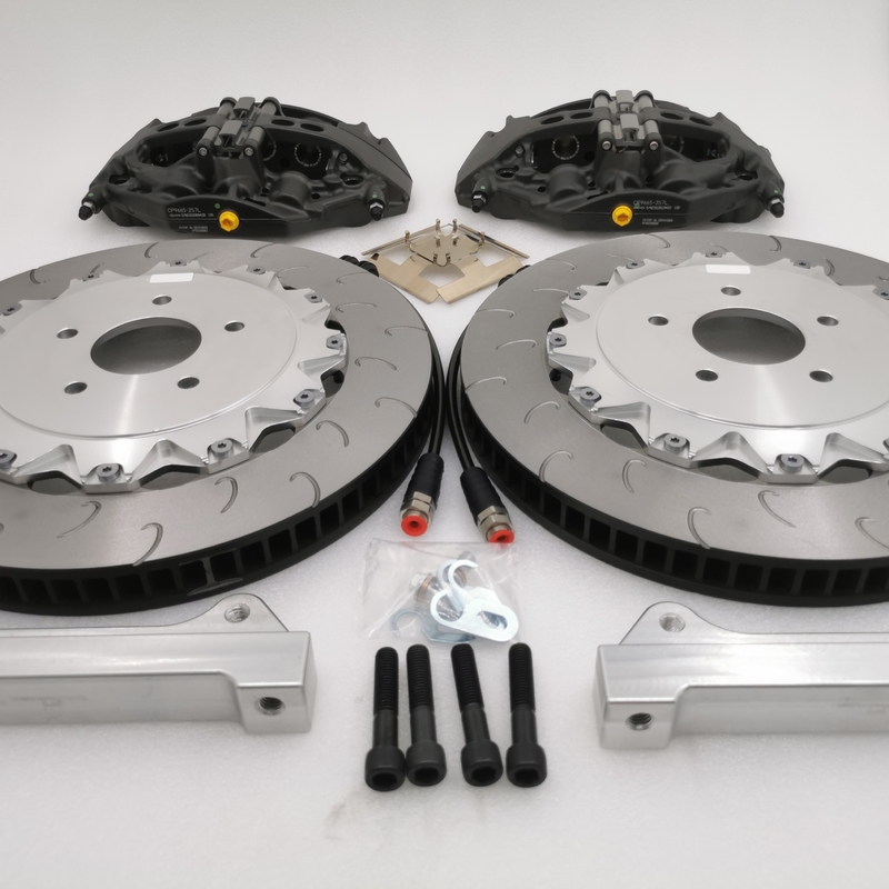
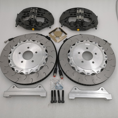
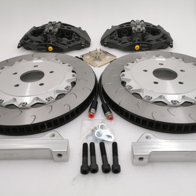
CP9665 6 Pot Brake Kit Original Caliper 390*36mm For 2015 NMW F80 M3
Braking System
1. Energy supply device: including various components that supply, adjust the energy required for braking and improve the state of the transmission medium
2. Control device: Various components that generate braking action and control braking effect, such as brake pedal
3. Transmission: including the various components that transmit braking energy to the brake, such as brake master cylinder, wheel cylinder
4. Brakes: Components that create an impediment to the movement or tendency of a vehicle to move
The braking system generally consists of two main parts: the braking control mechanism and the brake.
The basic structure of a general brake system
·It is mainly composed of wheel brake, hydraulic transmission and pneumatic transmission mechanism.
The wheel brake is mainly composed of a rotating part, a fixed part and an adjustment mechanism. The rotating part is the brake drum; the fixed part includes the brake shoe and the brake bottom plate; the adjustment mechanism is composed of an eccentric support pin and an adjustment cam for adjusting the clearance of the shoe drum.
·Hydraulic brake transmission mechanism is mainly composed of brake pedal, push rod, brake master cylinder, brake wheel cylinder and pipeline.
The pneumatic brake transmission mechanism is mainly composed of brake pedal, push rod, brake master valve, air dryer, four-circuit protection valve, brake air chamber and pipeline.
How the brake works
The general working principle of a braking system is to use the mutual friction between the non-rotating elements attached to the body (or frame) and the rotating elements attached to the wheels (or driveshafts) to prevent the wheels from turning or tending to turn.
1) When the brake system does not work
There is a gap between the shoe drums, and the wheels and brake drums can rotate freely
2) When braking
To decelerate the car, step on the brake pedal through the push rod and the master cylinder, so that the oil in the master cylinder flows into the wheel cylinder under a certain pressure, and the brake shoe is rotated around the support pin by the two wheel cylinder pistons, and the upper end is separated to both sides And its friction plate is pressed against the inner circular surface of the brake drum. The non-rotating brake shoe produces a friction torque on the rotating brake drum, thereby generating braking force
3) Release the brake
·When the brake pedal is released, the return position means that the brake shoe is pulled back to its original position, and the braking force disappears.
Structure and working process of brake master cylinder
The function of the brake master cylinder is to convert the mechanical energy input from the outside into hydraulic energy, so that the hydraulic energy is transmitted to the brake wheel cylinder through the pipeline
·The brake master cylinder is divided into single-chamber and dual-chamber types, which are respectively used for single-circuit hydraulic brake system and double-circuit hydraulic brake system.
1. Single-chamber brake master cylinder
1) When the brake system does not work
When not braking, the master cylinder piston is located between the compensation hole and the oil return hole
2) When braking, the piston moves to the left, the oil pressure rises, and the wheel brakes
3) Release the brake
Remove the pedal force, the return spring acts, the piston returns, the oil returns, and the brake is released
2. Dual-chamber brake master cylinder
1) Structure (such as the tandem dual-chamber brake master cylinder in the dual-circuit hydraulic brake system of the FAW Audi 100 sedan)
·The master cylinder has two chambers
The first cavity is connected with the right front and left rear brakes; the second cavity is connected with the left front and right rear brakes
·Each line and working chamber communicate with the oil storage tank through the compensation hole and the oil return hole respectively. The second piston is kept in the correct initial position by the right end spring, so that the compensation hole and the oil inlet hole communicate with the cylinder. The first piston is pressed against the sleeve under the action of the left end spring, so that it is in the position between the compensation hole and the oil return hole.
2) How it works
When braking, the first piston moves to the left and the oil pressure rises, which overcomes the elastic force and sends the brake fluid into the front right and left rear brake circuits; at the same time, the second piston is pushed to increase the hydraulic pressure in the second chamber, and the two-wheel brake move
·When the brake is released, the piston returns to the position under the action of the spring, and the hydraulic oil flows back to the brake master cylinder from the wheel cylinder and the pipeline. If the piston returns quickly, the volume of the working chamber also expands rapidly, so that the oil pressure decreases rapidly. The oil in the liquid storage tank can flow into the working chamber through the oil inlet hole and the small hole above the piston to push the sealing ring open. When the piston is fully returned, the compensation hole is opened, and the excess oil in the working chamber flows back to the liquid storage tank from the compensation hole. If the hydraulic system is due to oil leakage and the expansion or contraction of the oil in the main cylinder working chamber, pipeline and wheel cylinder due to temperature changes, it can be adjusted through the compensation hole.
Structure and working process of brake wheel cylinder
·The function of the brake wheel cylinder: It is to convert hydraulic force into mechanical thrust. There are single piston and double piston.
1) Structure
·The double-piston wheel cylinder of Audi 100 has two pistons and two cups. The spring makes the cups, pistons and brake shoes in close contact.
2) Working process
·When braking, hydraulic oil enters the oil cavity between the two pistons, and then pushes the brake shoes to open to realize braking.
·Bleeding bolts are provided on the wheel cylinder block to ensure sensitive and reliable braking.
| Item Name | 6 pots Auto brake caliper |
| Caliper Material | Cast Aluminum |
| Caliper color | Gray Caliper |
| Bell and bracket color | Silver Center Bell |
| Bell type |
New Center Bell |
| Caliper Material | Aluminum Cast |
| Logo | AP Racing logo |
| Disc type | J hook |
| For Wheel size | Rim 21 front |
| Full set included | 2xbrake caliper/2xbrake disc with center cap and bracket/ 2xbrake line/4xbrake pads |
![]()
![]()
![]()
Enter Your Message
| Guangzhou Yuanxing Industrial Co., Ltd. |
| Room 302, Building 5, No. 7, Wu Alley, Laowu Street, Dongping Village, Yongping Street, Baiyun District, Guangzhou |
| 86--18816787278 |
| 18816787278@163.com |